|
E |
Chemical
Plant Input: Standard Input Output: Standard Output |
|

Dealing with chemicals is a risky job,
particularly if it is reactive. Reactive chemicals can be dangerous if not
stored in an appropriate environment. As a result, sophisticated instruments
that can support real-time processing, is required while transferring a
reactive chemical from one part of a chemical plant to another one. However,
instruments that can ensure strictly real-time service, is too much costly
& hence chemical plants use networks that provide real-time transfer with
some tolerance.
 Let us be a bit
more elaborate. In our concerned chemical plant, there are V pits. Pits are
places where chemicals can be stored. In order to reduce cost, they are not
facilitated with reactive chemical handling environment. So, for every second
the reactive chemical stays in some of these pits, they are decayed by 1
milligram. The pits are numbered from 1 to V. There is a safe storage attached
to pit S. No time is required to move to the storage from pit S. There is some
reactive chemical weighing W milligram in pit 1 at time 0. This chemical is to
be transported to the safe storage. Note that, the safe storage door is opened exactly
at time T. So, if the chemical reaches the storage before time T, you will have
to accept decaying of the chemical whereas if it reaches after time T, it can
not enter the safe storage. There are E transfer tubes in the network. The
transfer tubes have suitable environment for storing reactive chemicals inside
them. So, the chemicals are not decayed inside the tubes. Each transfer tube
connects two pits with an entry point in pit s and an exit point in pit d. For
each tube t, the entry point door is opened for any 1 second between time sst
& sct (sst ≤ sct) but we don't exactly know in which second it is
opened. Similarly, the exit point door is opened for any single second between
time dst & dct (dst ≤ dct). As you don't know the exact timing of the
doors' opening, if we want to move the chemical from pit s to pit d using tube
t, it must be available at pit s no later than time sst. If the chemical
reaches a particular pit x using tube y with exit point range dsy & dcy
(dsy ≤ dcy ) & leaves this pit using tube z with entry point range
ssz & scz (ssz ≤ scz), the maximum possible decay in that pit is scz
– dsy. Please note that, while choosing the tube to get out from a pit, you
must always select a tube with it's opening interval beginning no sooner than
the latest possible time for the chemical to enter that pit. For instance, in
the 3rd sample test case, the chemical will always leave pit 2 using the 3rd
edge even if it reaches pit 2 at time 15.
Let us be a bit
more elaborate. In our concerned chemical plant, there are V pits. Pits are
places where chemicals can be stored. In order to reduce cost, they are not
facilitated with reactive chemical handling environment. So, for every second
the reactive chemical stays in some of these pits, they are decayed by 1
milligram. The pits are numbered from 1 to V. There is a safe storage attached
to pit S. No time is required to move to the storage from pit S. There is some
reactive chemical weighing W milligram in pit 1 at time 0. This chemical is to
be transported to the safe storage. Note that, the safe storage door is opened exactly
at time T. So, if the chemical reaches the storage before time T, you will have
to accept decaying of the chemical whereas if it reaches after time T, it can
not enter the safe storage. There are E transfer tubes in the network. The
transfer tubes have suitable environment for storing reactive chemicals inside
them. So, the chemicals are not decayed inside the tubes. Each transfer tube
connects two pits with an entry point in pit s and an exit point in pit d. For
each tube t, the entry point door is opened for any 1 second between time sst
& sct (sst ≤ sct) but we don't exactly know in which second it is
opened. Similarly, the exit point door is opened for any single second between
time dst & dct (dst ≤ dct). As you don't know the exact timing of the
doors' opening, if we want to move the chemical from pit s to pit d using tube
t, it must be available at pit s no later than time sst. If the chemical
reaches a particular pit x using tube y with exit point range dsy & dcy
(dsy ≤ dcy ) & leaves this pit using tube z with entry point range
ssz & scz (ssz ≤ scz), the maximum possible decay in that pit is scz
– dsy. Please note that, while choosing the tube to get out from a pit, you
must always select a tube with it's opening interval beginning no sooner than
the latest possible time for the chemical to enter that pit. For instance, in
the 3rd sample test case, the chemical will always leave pit 2 using the 3rd
edge even if it reaches pit 2 at time 15.
Write a program to find a way to transfer the chemical from
pit 1 to the safe storage with maximum guaranteed weight left (in milligram) in
the storage i.e. with minimum guaranteed decay. Please note that, the chemical
can not have negative weight at any point.
Input
The input file contains multiple test cases. First line of
each test case contains three integers, V (1≤V≤50,000 ), E (1≤E≤100,000
) & W (1≤W≤2,000,000,000 ). The next line has two integers, S
(1≤S≤V) & T (0≤T≤2,000,000,000)
Each of the following E lines describes a tube. A
Tube t is described with 6 integers, s
(1≤s≤V), d (1≤s≤V), sst, sct, dst, dct (0≤sst≤sct<dst≤dct≤2,000,000,000
) where s, d, sst, sct, dst & dct holds the meaning as in problem
statement.
The end of input is denoted with a case where V = E = W =
0. This case should not be processed.
Output
For each test case, print a single line of the form,
“Plant C: L” where C is the test case
number and L is the weight of the chemical available in the safe storage at
time T.
Sample Input Output for Sample Input
|
3 6 50 2 50 1 2 0 10 20 30 1 2 5 6 9 11 2 3 13 15 25 28 3 3 32 33 40 45 3 1 30 31 39 40 1 2 41 42 48 49 5 13 20 3 1000 3 3 41 41 999 1000 3 3 39 40 1000 1000 5 4 25 25 30 30 1 2 2 2 6 6 1 2 1 1 8 8 2 2 7 7 13 13 2 2 8 8 15 15 2 3 14 14 20 20 2 3 16 16 20 20 4 3 30 30 40 40 4 3 32 32 41 41 3 5 21 21 25 25 3 5 22 22 25 25 3 3 50 3 30 1 2 5 10 15 25 2 3 20 20 30 30 2 3 25 25 30 30 0 0 0 |
Plant 1: 27 Plant 2: 15 Plant 3: 30 |
|
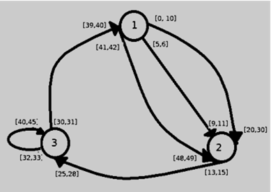
1st
Sample Illustration:
The above diagram
depicts the first case in sample. The chemical starts at time 0 in pit 1.
Then goes to 2 by the ([5,6] [9,11]) edge. Minimum guaranteed decay at 1 is
6. Then 2 to 3 via the ([13,15] [25,28]) edge. Minimum guaranteed decay is 6.
Then 3 to 1 through tube ([30,31] [39,40]). Again with 6 minimum guaranteed
decay. Finally 1 to 2 by the ([41,42] [48,49]) edge. The minimum guaranteed
decay is 3 at node 1 & 2 at the destination. |
Problem setter: Mohammad Mahmudur
Rahman, Special Thanks: Derek Kisman